
- Traceability Suite
- MatrixEx
MatrixEx Add-In
The Extended Matrix (MatrixEx) Add-In allows you to view relationships between elements in packages or on a diagram according to various criteria. As a matrix view, you can see which elements are placed in diagrams, and relationships between elements and classifiers of the elements.
This page contains the following topics.
- Features
- How to Use
- How to Specify Criteria
- Matrix View
- Example: Relationships between elements in a package and on a diagram
- Example: Relationships between elements in packages
- Example: Elements and diagrams in which the elements are placed
- Example: Display packages as the same as elements
- Example: Relationships between classifiers of elements and elements placed within another element
- Example: Two-hop relationships
- Expanding and Collapsing the Tree
- Editing connector properties
- Use of Specification Elements and Exporting Matrix Image
- Exporting and Importing Profiles
- Overlays
- Zoom in/out
- Options
- Customize Types of Elements, Connectors and Diagrams
Features
The MatrixEx Add-In has more features than the built-in Enterprise Architect Relationships Matrix feature. The following are some of the MatrixEx features.
Matrix Sources and Targets
- Drag and drop a package from the Browse window as source or target
- Specify a diagram as source or target, all elements in the diagram are displayed
- Conditional search by element name, stereotype, or tagged value
- Specify multiple element types and connector types
View
- Tree view on source page, half-tree view on target page
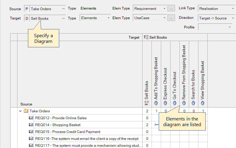
- Target diagrams to view placement of elements on each diagram (Example)
- Display relationship between element classifier and elements placed within the element (Example)
- Display two-hop relationship between elements (Example)
- Conditional row and column highlighting
Other Features
- Locate source or target element in diagrams or the Browser
- Export matrix image to the Linked Document
- Customize target types of elements, connectors, etc. via Ini file
- Export matrix to Excel, RTF, HTML, etc.
and much more...
How to Use
After installing the Add-In, click the 'MatrixEx' button on the 'Specialize' ribbon, 'Add-Ins' panel. You need to open a project before opening MatrixEx view.
Immediately after applying a new license, there is no 'MatrixEx' button on the ribbon. Please restart Enterprise Architect.
How to Specify Criteria
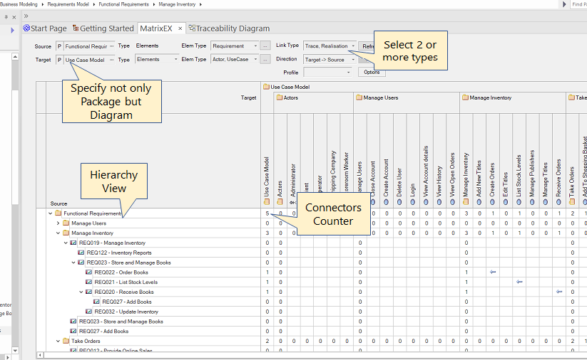
Specify Source and Target
There are two ways to specify the source and target.
- By specifying conditions in the Condition panel (in this page, we call this mode 'Basic Matrix')
- By dragging and dropping a package from the Browser window onto the matrix column or row header. (in this page, we call this mode 'D&D Matrix')
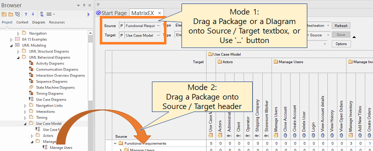
Mode 1 (Basic Matrix) and Mode 2 (D&D Matrix) cannot be used together. Changing the mode (i.e., specifying a source or target package in the Criteria panel, or dragging and dropping a package) clears the current information in the matrix.
D&D Matrix
You can drag and drop a Package from the Browser window onto the Matrix. To specify multiple Packages, drag a Package one by one.
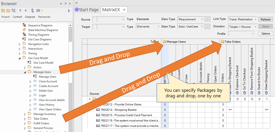
- Only packages can be dragged and dropped.
- After you have specified source and target packages, you must specify element types, connector types, and direction in the Criteria panel.
- You can specify a package to source or target in the following rule:
- If there is no package in the source or target, the source or target is determined depending on whether the dropped position is closer to the left end (source) or the top end (target) of the matrix.
- If there is a package in the source or target, you can add a package by dropping it on the column or row header.
- If you drop a package that has already been added to the column or row, the following rule applies:
- If there is the same package and some of the subpackages are hidden, the hidden packages are shown again.
- If the parent package of the dropped package is already added, the dropped package is added below the parent package.
- If the child package of the dropped package is already added, the child package is moved below the dropped package.
You can use the context menu to hide parts of rows and columns. You can also use the context menu to clear the entire contents of the matrix.
When you hide rows or columns, they remain hidden even if you refresh the contents or save as a profile.
Criteria Panel
Specify criteria to be displayed in the matrix as you wish. Some criteria can be set by dragging them from the Browser window. (This option must be enabled.)
The following table lists the items in the Criteria panel. Some items work differently when using the 'D&D Matrix' mode.
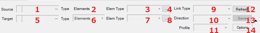
| # | Item | Description | D&D Matrix |
|---|---|---|---|
| Source side (vertical axis) | |||
| 1 | Target of Source side | - Click to display a dialog for selecting a package or diagram - When a package is selected, 'P' is displayed. When a diagram is selected, 'D' is displayed - You can drag and drop a package or a diagram from the Browser window * |
Not used |
| 2 | Type to display | currently, fixed type: 'Elements' | |
| 3 | Type(s) of Source elements | - Two or more element types can be specified from this dropdown list - You can specify a type by drag & drop an element from the Browser window * | |
| 4 | Detail specification of Source | You can filter items by name, stereotype, or tagged value. | |
| Target side (horizontal axis) | |||
| 5 | Target of Target side | The same as Item 1 | Not used |
| 6 | Type to display | - You can specify 'Elements', 'Diagrams', 'Elements in Elements', 'Two-hop Relation' - See here for details about 'Two-hop Relation' |
'Elements' only |
| 7 | Type(s) of Target | - If 'Elements in Elements' is specified in Item 6, you must specify both element types and diagram types - Two or more types can be specified from this drop down list - You can specify a type by drag & drop an element or a diagram (depends on Item 6) from the Browser window * |
|
| 8 | Detail specification of Target | The same as Item 4, but 'Type' must be 'Elements' to use this button | |
| Connectors | |||
| 9 | Type(s) of connectors | - Active if Item 6 is 'Elements' - Two or more types can be specified from this drop down list |
|
| 10 | Direction of connectors | - Active if Item 6 is 'Elements' - Multiple directions can be specified |
|
| Buttons | |||
| 11 | Profile | You can reuse the same combinations of criteria by creating a Profile. Items between 1 and 10 are stored in a Profile | |
| 12 | Refresh | Refresh the matrix to show the latest information | |
| 13 | Save | Save the changes in the matrix to the model. Active when there are unsaved changes. | |
| 14 | Options | - Export: Export the matrix to various types of files - Profile: Create, update and delete profiles, or create a Matrix specification element - Options: Specify various types of options |
|
*: You must enable the Option: 'Enable Drag and Drop Operation' option.
Detail Specification Dialog
This dialog allows you to specify element criteria to be displayed in the matrix.
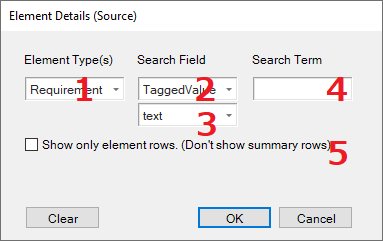
| # | Item | Description |
|---|---|---|
| 1 | Element Type(s) | Two or more types can be specified from this dropdown list |
| 2 | Search Field | Select one of 'Name', 'Stereotype', or 'TaggedValue' |
| 3 | Search Tag Name | - Select or enter target Tagged Value name (Exact match) - This field is displayed when Item 2 is 'TaggedValue' |
| 4 | Search Term | Enter search term for Item 2:
|
| 5 | Show only element rows | Summary rows or columns will not be shown in the matrix |
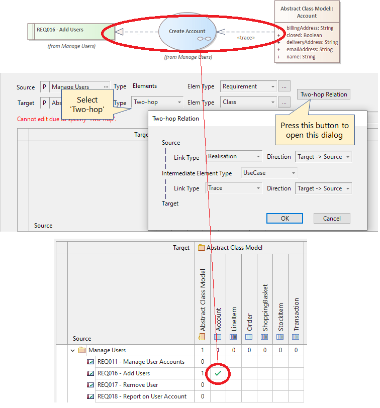
Two-hop Relation Settings
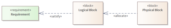
Specify the type and direction of connectors with the intermediate elements between the Source and the Target, and the types of the intermediate elements.
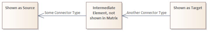
One of the use cases of this relation is the following SysML relation. By using this 'Two-hop' relation, you can see a matrix between Requirements and physical Blocks in the following connectors between elements.
Two-hop Relation Settings Dialog
In the main criteria panel, select 'Two-hop' rom the Target side Type drop-down list. The Two-hop button appears. Clicking this button displays the Two-Hop Relation dialog box.
Specify intermediate element types, connector types, and direction to/from intermediate elements
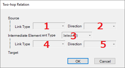
| # | Item | Description |
|---|---|---|
| 1 | Types of connectors (Source - Intermediate) | You can specify multiple types |
| 2 | Directions of connectors (Source - Intermediate) | You can specify multiple directions |
| 3 | Types of intermediate elements | You can specify multiple types |
| 4 | Types of connectors (Intermediate - Target) | You can specify multiple types |
| 5 | Directions of connectors (Intermediate - Target) | You can specify multiple directions |
Matrix View
Once all criteria are specified, the Matrix view will automatically appear as shown below.
(Depending on the options, you may need to click the Refresh button.)
If you change the criteria, the view will be updated with the new criteria. You can see the latest information by clicking the Refresh button.
When the view is refreshed, the packages on the Source page are expanded.
By default, the order of packages and elements is the same as in the Browser window.
Here are some examples of the Matrix view.
Example: Relationships between elements in a package and on a diagram
Adding or Deleting Connectors
To add or delete a connector, do one of the following in a target cell:
- Double-click *
- Press the space bar *
- Right-click and select Connector Type from the shortcut menu
When you add a new connector, the arrow icon appears in the cell. When you delete a connector, the arrow icon disappears. In both cases, the background of the cell is yellow, which means that the change is not yet saved. When you are finished, click the Save button to save the changes. If more than one connector directions are specified as criteria, you cannot add or delete connectors.
*: This method is available only when only 1 connector type is specified.
Actions for a Diagram/Element
When you select an item in the Source or Target header, the item will be highlighted in the Browser window. You can perform an action by double-clicking on an item:
- Diagram: Open the diagram
- Element: If you specify 'Diagram' as Target, open the diagram and select the double-clicked element in the diagram.
Displaying multiple connector types
When two or three connector types are specified, the color of the arrowhead icons is differentiated for each the connector type and the legend is displayed.
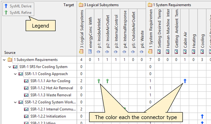
The legend is not included in the export file.
Displaying child elements' connectors as parents' connectors as well
By using the option, you can display child elements' connectors as parents' connectors using the white arrowhead icon.
![]()
The white arrowhead icons are not included in the export file.
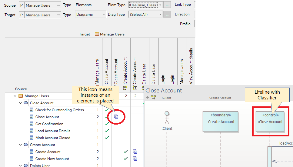
Example: Elements and diagrams where the elements are placed
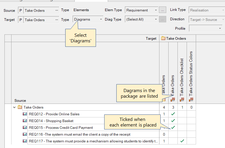
You can optionally display diagrams in child packages. The hierarchy drawing of the Target side is different from the Source side.
You can check the usage of instances in diagrams using the special icon.
Example: Displaying packages as the same as elements
The rows and columns of packages show the number of connectors, but you can also display packages themselves as the same as elements. You can add or remove connectors as shown below.
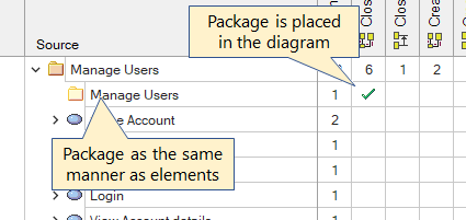
If you want to display packages as the same as elements (as shown above), you must edit the Ini file. For more information on how to edit the Ini file, please see here.
Example: Relationships of 'Elements in Elements'
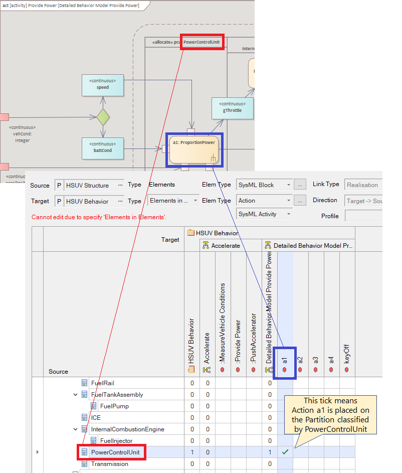
In the Target side, only elements in another element are displayed. (In the figure above, the Target side Actions are placed in the classified Partitions.)
By using this 'Elements in Elements' matrix, you can assign actions (i.e., features) to each SysML Block in Activity diagrams, and also check all assigned features for each Block through this matrix.
Example: Two-hop Relationships
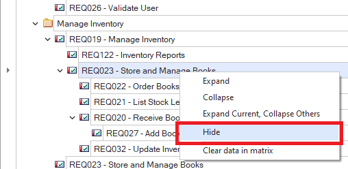
Expanding and Collapsing the Tree
You can expand and collapse the tree by using the context menu (right-click) of the tree as shown below.
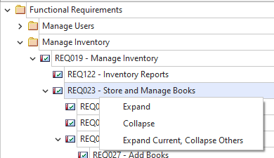
The 'Expand Current, Collapse Others' menu is useful when you want to focus on the elements contained in the selected item.
Editing connector properties
You can edit the connector properties (Name, Alias and Notes) in the dialog by using ENTER on the cell that has arrowhead icon as shown below.
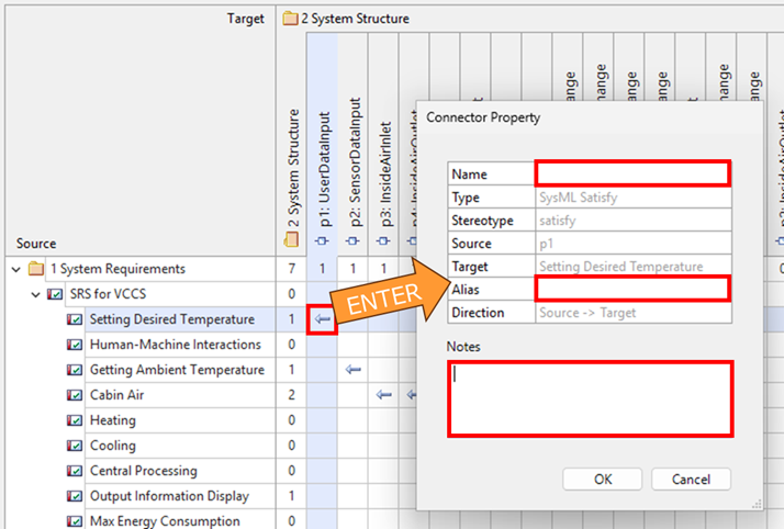
When the cell that has one relationship only, you can use this feature.
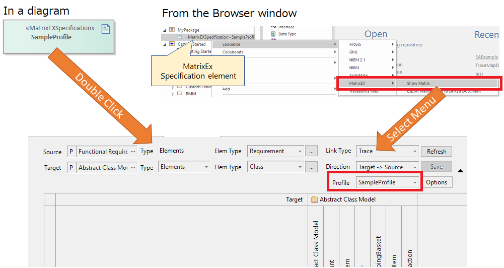
Using Specification Element (Shortcut Element)
Using MatrixEx Specification Elements
You can create a MatrixEx specification element (shortcut element) by specifying an existing profile to easily open the MatrixEx. For example, if you double click on a specification element placed on a diagram, it will display the MatrixEx view with the specified profile.
Creating a Specification Element
To create a specification element, you must add and activate a target profile.
When you select a target diagram, a specification element is created under the package of the diagram and the element is placed on the diagram.
Displaying MatrixEx from a Specification Element
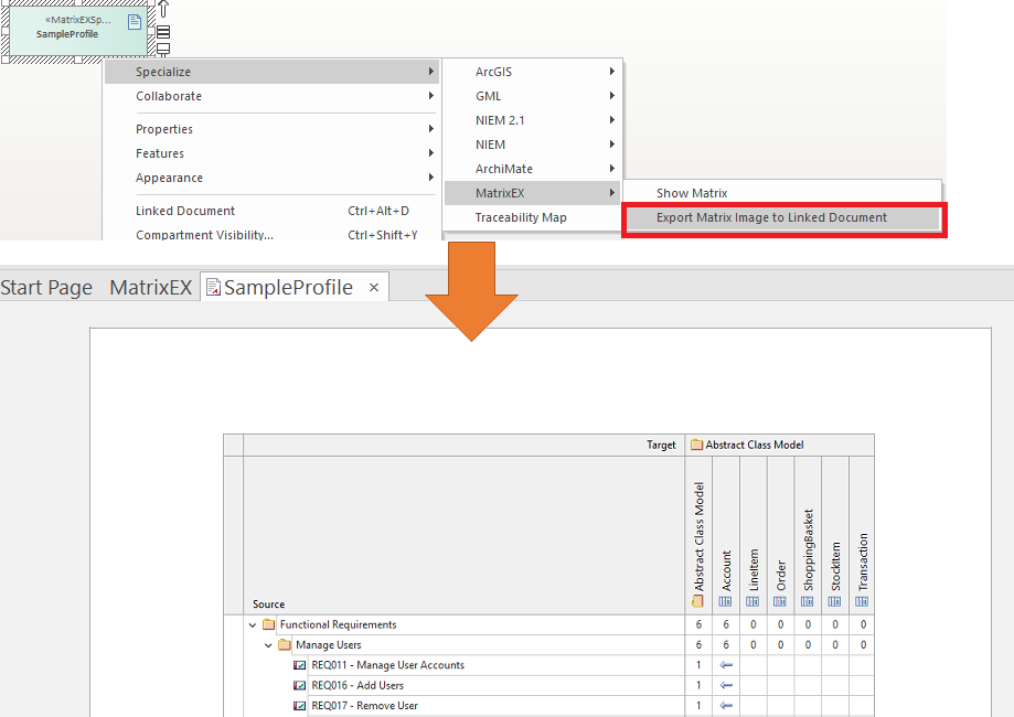
Exporting a Matrix Image to a Specification Element
You can export a matrix image as a linked document of the specification element. The matrix image in the linked document can be used in the Enterprise Architect's built-in document generation.
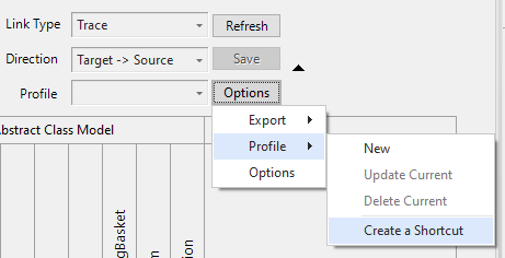
Exporting and Importing Profiles
Profiles can be exported and imported using the built-in XMI export and import feature for the specification elements described above. After import, double-clicking on a specification element will create a profile and display with the profile criteria in the MatrixEx.
If a profile with the same name as the specification element already exists, the existing profile is used. (not overwritten)
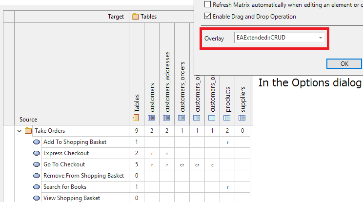
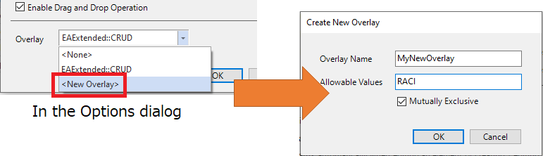
Overlays
The arrowhead icons in cells can be changed to a CRUD-like format or any characters as you like. By using overlay feature, you can show additional information to connectors in the matrix.
- Overlays can be applied only when the Target side is 'Elements'.
- Overlays will not be applied when some options are enabled.
- This overlay setting is compatible with the EA build-in overlays feature.
Example of a CRUD overlay
How to edit an overlay
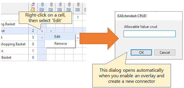
How to add a new overlay
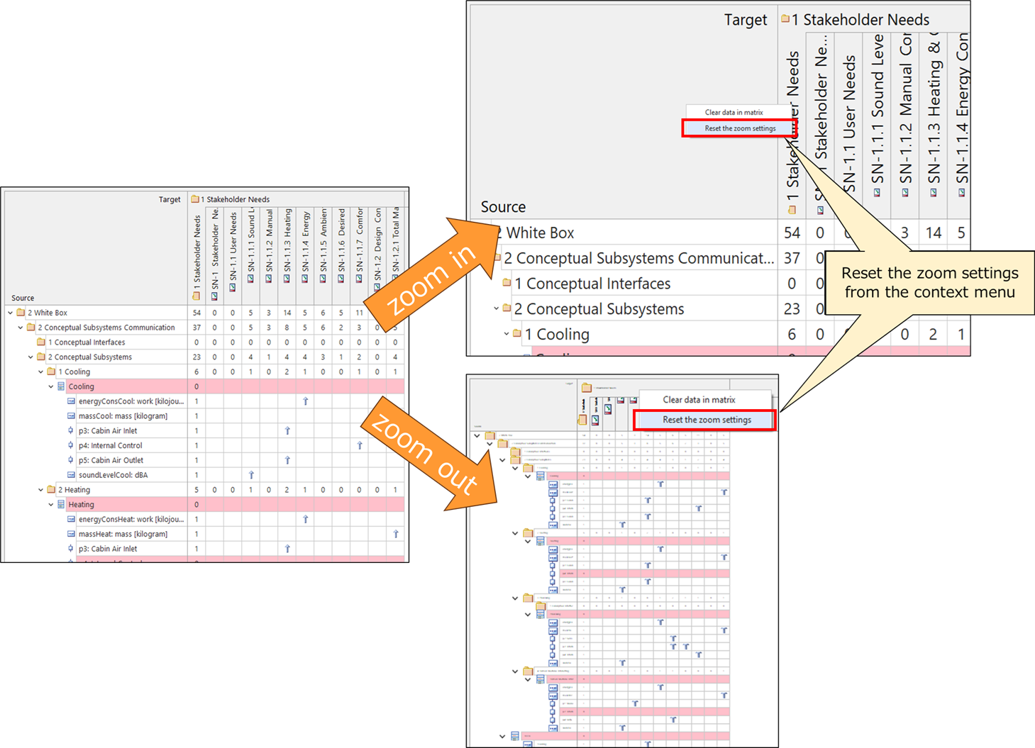
Zoom in/out
You can zoom in/out the matrix with CTRL + Mouse Scroll Wheel. (This feature does not work when editing the matrix or using the 'D&D Matrix'.)
Options
You can set the following options. These options are retained even after this Add-in is closed. (except those marked with *)
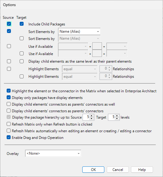
- Include Child Packages
- Sort Element by: specify sorting target (Name (or Alias if next option is enabled), or Tagged Value)
- Use Alias if Available
- Display child elements as the same level as their parent elements
- If this option is enabled and target element types do not include parent types, only child elements will be displayed.
- Valid only when Source/Target is a package and display types are 'Elements'
- Show only child elements when specifying only their types
- Highlight elements under specified condition
- Highlight the element or the connector in the Matrix when selected in Enterprise Architect
- Display packages which have one or more matched elements, and hide empty packages
- Display child elements' connectors as parents' connectors as well
- Display child elements' connectors as parents' connectors
- If this option is enabled, Child elements will not be displayed.
- Valid only when Source/Target is a package and display types are 'Elements', and in the Basic Matrix mode
- Display the package hierarchy up to specified levels
- Refresh Matrix only when the Refresh button is clicked
- Valid only in the Basic Matrix mode
- Refresh Matrix automatically when editing an element or creating / editing a connector *
(will be reset to disabled after closing the Add-in) - Enable Drag and Drop Operation
- Overlay: select existing a overlay or define a new overlay
- Valid only when both display types are 'Elements'
Customize Types of Elements, Connectors and Diagrams
The types of elements, connectors, and diagrams to be displayed are set in the Ini file as follows. You can add, delete, change the order and rename them.
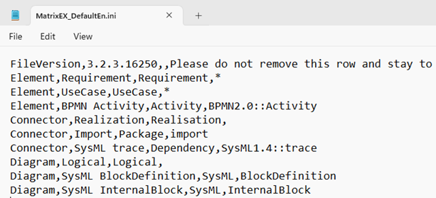
When this Add-In is installed, the default Ini file (MatrixEX_DefaultEn.ini) is installed in the Enterprise Architect installation directory.
How to Edit the Ini File
Steps
- Copy the MatrixEX_DefaultEn.ini file into the folder described below
- Edit the copied Ini file
Details
Ini File Requirements:
- The name of the Ini file must be MatrixEX_*.ini (* is any string)
- The Ini file is placed in the Windows MyDocuments folder (e.g., C:\Users\<your_name>\Documents)
- Only one Ini file can be placed
- Character set of the file is UTF-8
- When Enterprise Architect is started, the Add-In loads the Ini file.
- When there is no Ini file in the MyDocument folder, the Add-In loads the Ini file in the Enterprise Architect installation directory.
- If there are more than one Ini file in each case, the Add-In shows an error and is deactivated.
Ini File Specification:
- One element, one connector, or one diagram type can be set per line
- Each line contains the following information, separated by commas (CSV format)
- Item 1: One of 'Element', 'Connector', or 'Diagram'
- Item 2: Display name
- Item 3: Type of the element, connector, or diagram
- Type string must match the internal string in Enterprise Architect
- When Item 1 is 'Diagram' and if you want to specify a non-UML diagram (i.e., defined by a profile), Item 3 should be the profile name and Item 4 should be the stereotype of the diagram.
- Item 4: Stereotype
- When Item 1 is 'Element', '*' means that elements of all stereotypes are included.
- When Item 1 is 'Connector', a fully qualified stereotype name can be specified.
- If you leave this item blank, it does NOT mean that any stereotype is matched. When blank, elements (,connector, or diagram) with any stereotype are not included.
- The display order in the Criteria panel is the same as order in the Ini file.
- If you want to display packages as the same manner as elements, copy the next line of the '//Package element' definition in the MatrixEX_SampleEn.ini file and paste it in your Ini file. The sample file is installed as 'sample_MatrixEx' directory in the Enterprise Architect installed directory.
Notes
- MatrixEX_DefaultEn.ini in the Enterprise Architect installed directory will be always overwritten when the Add-In is installed or updated. When you want to customize, please copy this Ini file to the MyDocument folder.
- Elements, connectors, and diagrams in the matrix are limited to types defined in the ini file. If you select '(Select All)' in the Criteria panel, it means all types listed in the dropdown list. 'All' does NOT mean all types are included.
- To know how to add non-UML types to the Ini file, please see the MatrixEX_SampleEn.ini file in the sample_MatrixEx folder of the Enterprise Architect installed directory.
How to update your Ini file to the latest version
When you install a newer version of the Add-In, you may get a message that your Ini file is out of date and may need to be updated. In this case, if you will not update your Ini file, the Ini file might not be loaded correctly and the Add-In might not work properly. Therefore, please follow the steps below to check and update the contents of the Ini file.
- Open your Ini file in text editor
- See the change log about the ini file, and
- If you want to use [Added] marked line, add it to your Ini file
- If there is a [Changed] line and you use the line, copy the line from the change log and overwrite it in your Ini file
- If there is a [Deleted] line and you do not use the line, delete the line from your Ini file
- Copy the first line of MatrixEX_DefaultEn.ini and overwrite as the first line of your Ini file (the first line contains version information)
- Restart Enterprise Architect after saving the changes.